Page #9 |
INSTALLATION MANUAL |
STEP 3: PAGE 3 OF 3 |
FRONT WALL INSTALLATION
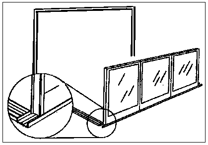
DIAGRAM 3.4

DIAGRAM 3.4
After any cutting on the front wall modules, place the correct numbered module or solid fill panel starting at the left side. The layout sheet will note solid or window module on the corners of the front wall. The left end of the Module or solid should intersect the inside corner of the Sidewall Bottom Track & Front Wall Track. Make sure the weep holes of the window modules are facing out. (If there is any solid on the sides of the front wall, place these in the same position as you would with a starting module). Add all other front wall Modules to the first one in their correct order, mating the with the males and female extrusion.
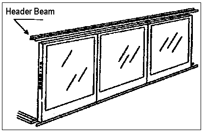
DIAGRAM 3.5

DIAGRAM 3.5
Place the Header Beam on top of the front Wall. This Header should overhang the sides of the front wall at the same distance as the Front Wall Bottom Track ( 2 1/8" on a 2" wall and 3 1/8" on a 3" wall measured from the outside web of the vertical mullion). Be sure that the electrical raceways in the walls line up with the chase nipples in the Header.
There are pre-punched holes on the top of the Header beam (curved roof) which line up with the vertical mullions in the front wall. The holes are guides to placing the rafters in their proper postion. There are holes in the Attachment Channel for the same purpose. There are no pre-punched holes for Straight Eave Headers or Attachment Channel.
A rafter or roof panel may be used to steady the front wall as you secure it to the header & bottom track.